Categories
Senza categoria

The correct use of switches and limit switches as interlocking devices

It frequently happens that a machine has guards designed to protect the operator from contact with moving parts and that these guards must be opened during normal use of the machine or for maintenance.

A switch is often installed near these guards which, in the event of opening, sends feedback to the machine control system and brings the machine to a safe condition, stopping the moving parts.

A switch that monitors the position of a guard is, in all respects, a safety component and therefore its choice and correct use are elements to be carefully analyzed to ensure the safety of a machine. As a regulatory reference, consider the:

EN ISO 13849-1:2015 – Safety of machinery – Safety-related parts of control system – Part 1: general principles for design.

This standard forms the basis for the functional safety of the machinery; inside, regarding the monitoring of the safeguards, is mentioned the:

EN ISO 14119:2013 – Safety of machinery – Interlocking devices associated with guards – Principles for design and selection

The latter constitutes a normative reference for the techniques and devices to be used for monitoring the safeguards.

Mechanical switches that are safety components must bear the symbol on their casing:

Furthermore, it is necessary that they work in “normally closed” mode, ie with contacts closed when the safeguard is closed (safe position), unless more than one is mounted on the same safeguard and there is a monitoring system for their consistency and plausibility. Switches with this symbol incorporate mechanisms within them such that their electrical contacts, under the pressure of the actuator, open even if they are glued together. In extreme situation, the contacts even break irreparably, but open equally. In this way, the feedback to the machine control system about the status of the safeguard is guaranteed.

The assembly of the interlocking devices also deserves a closer look. The standards in fact establish that their operation is guaranteed by the mechanical movement consequent to the opening of the guard and is absolutely not entrusted to gravity or springs. In this way, in fact, the probability that a failure of the spring leads to a false “safe position” signal to the control system is reduced..

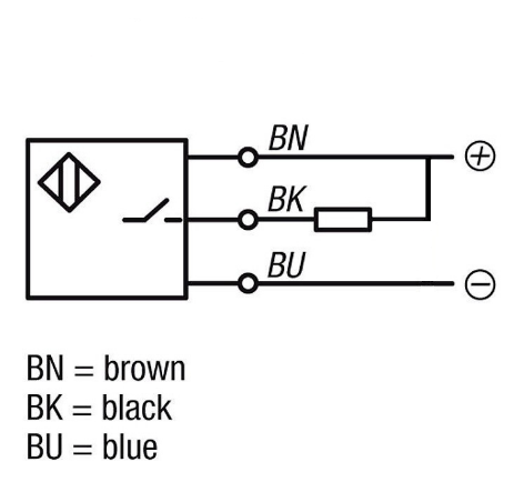
So installations of this type are NOT absolutely adequate:

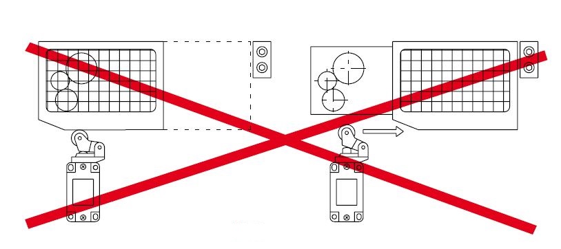
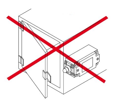
In such situations, in fact, the breakage of the switch spring or the bonding of the contacts would lead to the possibility of opening the guard without the machine stopping.

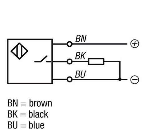
Instead, installations like the following are correct:

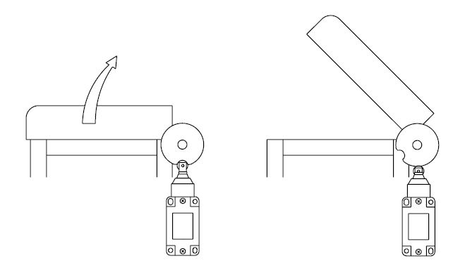
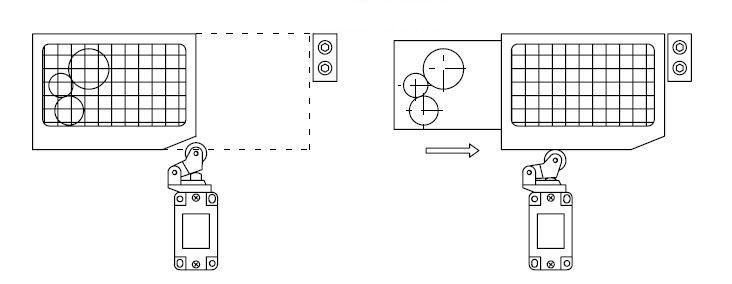
In fact, with these configurations, the opening of the guard acts mechanically with a positive action on the switch actuator, therefore even in the event of a spring failure or contact sticking, the opening of the electrical circuit is still guaranteed.

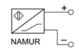
On the market there are also proximity sensors with various safety features. By the combined use of multiple devices of this type it is possible to reach very high safety levels (PL e according to EN ISO 13849-1 or SIL 3 according to EN ISO 62061). These sensors do not require mechanical contact between the sensor itself and the guard to be monitored.

There are also sensors of the “coded” type, that is sensors that detect only a particular type of target and therefore an intentional bypass is particularly difficult. Among the various technologies available on the market for this type of device, we mention RFID:

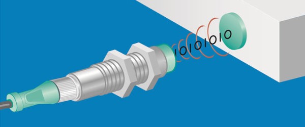
They send radio waves to the target, which responds by sending back a 32 or 64 bit binary code to the sensor; the sensor will activate its output only when it receives the same code with which it was programmed by the manufacturer. There are RFID sensors with two-channel output and self-diagnosis that can reach PL e or SIL 3 even with a single sensor.

Categories
Senza categoria

NPN and PNP sensors for automation

In the field of industrial automation, the most disparate types of sensors for various physical quantities are used.

Digital output sensors, that is, sensors whose logic output can only take on two states (typically “object present” and “not present”) are divided, classifying them according to the electrical type of their outputs, into two main categories: PNP and NPN.

The differences between the two types concern the method of connecting the load to be controlled.

NPN SENSORS:

The sensor output is normally floating (open collector), therefore it can be considered virtually isolated and free of voltage. When active, the sensor output is brought to ground by the electronics inside the sensor itself. One end of the load is permanently connected to the positive supply, while the other end, through the sensor, is connected to ground when the sensor output is activated.

PNP SENSORS:

The sensor output is normally floating (open collector), therefore it can be considered virtually isolated and free of voltage. When active, the sensor output is brought to the positive power supply by the electronics inside the sensor itself. One end of the load is permanently connected to ground, while the other end, through the sensor, is connected to the positive supply when the sensor output is activated.

The load is usually the photocoupled input of a PLC, however it is also possible to connect the sensor to the sensor, LEDs and other types of loads, taking care to check that the current absorbed by the load does not exceed the maximum current that can be supplied by the sensor.

The colors for coding the sensor wiring normally follow the following convention:

  • BLUE wire   ->   ground
  • BROWN wire   ->   + power supply
  • BLACK wire   ->   sensor output

NORMAL STATE OF THE OUTPUTS

Another fundamental parameter for choosing a sensor is the state of its output in a normal situation, that is, with the sensor not activated. In other words, when there are no objects to be detected in front of the sensor.

  • N.O. (normally open) output: the sensor output is not activated when the sensor is not triggered, it is activated when an object enters the sensor detection field
  • N.C. (normally closed) output: the sensor output is activated when the sensor is not triggered, it is deactivated when an object enters the sensor detection field

By combining the type of outputs with their rest state, there are a total of four possible configurations:

  • NPN – N.O. : NPN output, normally open
  • NPN – N.C. : NPN output, normally closed
  • PNP – N.O. : PNP output, normally open
  • PNP – N.C. : PNP output, normally closed
Categories
Senza categoria

NAMUR sensors: how they work and where to use them

The acronym NAMUR identifies a family of proximity sensors having a completely different type of output from that of the common NPN and PNP sensors.

The abbreviation NAMUR draws its origins from the German language and literally means “normenarbeitsgemeinschaft für Mess- und Regeltechnik in der Chemischen Industrie”, in other words “association for the standardization of measurement and control in the chemical industries”.

The standard symbol of NAMUR sensors is shown in the picture below:

As can be seen, the connection has two wires only since these sensors have current and not voltage outputs. The power supply necessary for the functioning of the electronics inside the sensor is also conveyed through these two wires.

The typical output characteristic of a NAMUR can be represented as follows:

In this case, as the distance S between the sensor and the object to be detected increases, there is an increase in the current in the sensor itself. The behavior can also be reversed, to provide the possibility of choosing between “normally open” and “normally closed” sensors. Although the graph may suggest analogue behavior, the NAMUR must be considered a digital sensor, with well established thresholds: the object is considered not detected for currents ≥2.1mA and detected for currents <1.2mA. The nominal no-load voltage at the ends of an interface for NAMUR sensor is 8.2V with an output impedance of 1kΩ. Such a low output impedance is intended and aimed at avoiding, in the event of a fault, the creation of possible ignition sources in the event of a fault. In addition to proximity sensors, there are also encoders with NAMUR output. Of course, for the correct use of devices with NAMUR output, it is necessary to use appropriately designed hardware. There are also conversion interfaces between NAMUR and NPN or PNP signals to allow the connection of NAMUR sensors to normal PLCs, as well as PLCs which natively have inputs suitable for the direct connection of NAMUR sensors.

The normative reference regarding the electrical output parameters of a NAMUR sensor is the EN 60947-5-6:2020 Low-voltage switchgear and controlgear – part 5-6: control circuit devices and switching elements – DC interface for proximity sensors and switching amplifiers (NAMUR).

NAMUR sensors are typically used in potentially explosive environments, as intrinsically safe devices: the energy that passes through them does not constitute an ignition hazard. If it is also necessary to have a certain degree of functional safety, if the sensor provides protection in this sense, safety hardware with NAMUR inputs is also available.

Categories
Senza categoria

Relationship between EN ISO 12100: 2010 AND Performance Level (PL) according to EN ISO 13849-1: 2016

The harmonized standard

EN ISO 12100:2010 – Safety of machinery – General principles for design – Risk assessment and risk reduction

constitutes a fundamental guide for all manufacturers who intend to CE mark their machinery according to the Machinery Directive 2006/42 / EC. It contains the basic principles for assessing the risk associated with a given machine and the guidelines for its reduction.

Chapter 6 is dedicated to this last fundamental aspect. The first paragraph highlights the levels to be taken to reduce risk:

  1. reduction of risks during design
  2. implementation of safety systems and / or complementary protection measures
  3. safety information for use

The order in which to undertake these actions must necessarily be that indicated above. The rationale behind this order invites manufacturers to take safety into account already in the design phase, where it is easier and above all more effective to make changes to the machine. All risks that cannot be reduced to acceptable levels simply by means of an intrinsically safe design must subsequently be mitigated by additional measures such as protections, guards and the like. Only as a last chance it is possible to use specific instructions and safety warnings reported in the machinery manuals.

The control system comes into play precisely in the second phase of risk reduction, especially in modern machinery which almost always integrates electromechanical and / or electronic components for their control. Where a function performed by a machine’s control system has direct repercussions on its safety, this function is called the “safety function”. Think, for example, of the classic red mushroom for emergency STOP. Or to a photoelectric barrier that stops the machine if an operator enters an unauthorized area.

The set of safety functions is called the “safety function list”. Each safety function must be appropriately characterized by a parameter that determines its efficiency in protecting against a risk of a given severity. For this purpose the standard has been prepared:

EN ISO 13849-1:2016 – Safety of machinery – Safety-related parts of control system – Part 1: General principles for design

In this standard, the characterization of each safety function is done by means of the parameter called “PLr”, short for “Required Performance Level”, indicating the minimum performance level that the safety function must reach in order to satisfactorily perform its action. The scale of possible performance levels is identified by lower-case letters of the alphabet, ranging from “a” to “e”, where “a” is the lowest possible level while “e” indicates the maximum achievable value.

For the determination of the PLr it is possible to follow the graph contained in Annex A of the standard.

Starting from the point indicated with “1”, this graph must be traveled from left to right, making appropriate choices at each crossroads, corresponding to the choice of the following parameters:

  • S: severity of injury
    • S1: slight (normally reversible injury)
    • S2: serious (normally irreversible injury or death)
  • F: frequency and/or exposure to hazard
    • F1: seldom–to-less–often and/or exposure time is short
    • F2: frequent-to-continuous and/or exposure time is long
  • P: possibility of avoiding hazard or limiting harm
    • P1: possible under specific conditions
    • P2: scarcely possible

Going through the graph in the figure and choosing the parameters S, F and P according to the specific cases, you reach one of the boxes corresponding to the PLr – required performance level.

The next step is to verify that the PL reached by the safety function is equal to or greater than the PLr. For this verification, the rule must be followed

EN ISO 13849-2:2013 – Safety of machinery – Safety-related parts of control system – Part 2: Validation