It frequently happens that a machine has guards designed to protect the operator from contact with moving parts and that these guards must be opened during normal use of the machine or for maintenance.
A switch is often installed near these guards which, in the event of opening, sends feedback to the machine control system and brings the machine to a safe condition, stopping the moving parts.
A switch that monitors the position of a guard is, in all respects, a safety component and therefore its choice and correct use are elements to be carefully analyzed to ensure the safety of a machine. As a regulatory reference, consider the:
EN ISO 13849-1:2015 – Safety of machinery – Safety-related parts of control system – Part 1: general principles for design.
This standard forms the basis for the functional safety of the machinery; inside, regarding the monitoring of the safeguards, is mentioned the:
EN ISO 14119:2013 – Safety of machinery – Interlocking devices associated with guards – Principles for design and selection
The latter constitutes a normative reference for the techniques and devices to be used for monitoring the safeguards.
Mechanical switches that are safety components must bear the symbol on their casing:

Furthermore, it is necessary that they work in “normally closed” mode, ie with contacts closed when the safeguard is closed (safe position), unless more than one is mounted on the same safeguard and there is a monitoring system for their consistency and plausibility. Switches with this symbol incorporate mechanisms within them such that their electrical contacts, under the pressure of the actuator, open even if they are glued together. In extreme situation, the contacts even break irreparably, but open equally. In this way, the feedback to the machine control system about the status of the safeguard is guaranteed.
The assembly of the interlocking devices also deserves a closer look. The standards in fact establish that their operation is guaranteed by the mechanical movement consequent to the opening of the guard and is absolutely not entrusted to gravity or springs. In this way, in fact, the probability that a failure of the spring leads to a false “safe position” signal to the control system is reduced..
So installations of this type are NOT absolutely adequate:
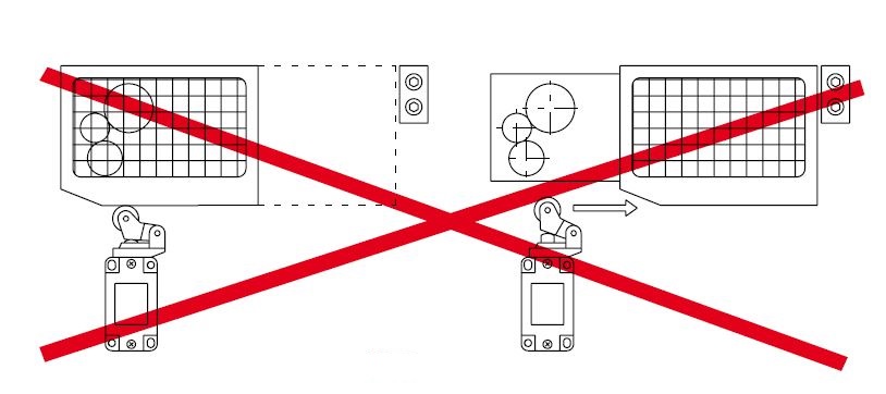
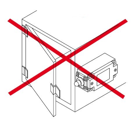
In such situations, in fact, the breakage of the switch spring or the bonding of the contacts would lead to the possibility of opening the guard without the machine stopping.
Instead, installations like the following are correct:
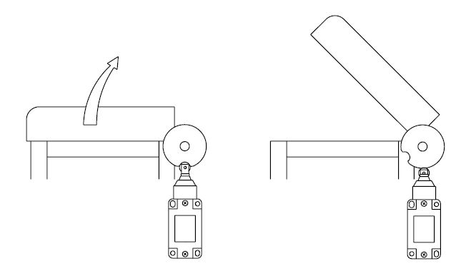
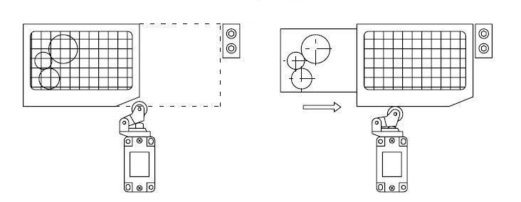
In fact, with these configurations, the opening of the guard acts mechanically with a positive action on the switch actuator, therefore even in the event of a spring failure or contact sticking, the opening of the electrical circuit is still guaranteed.
On the market there are also proximity sensors with various safety features. By the combined use of multiple devices of this type it is possible to reach very high safety levels (PL e according to EN ISO 13849-1 or SIL 3 according to EN ISO 62061). These sensors do not require mechanical contact between the sensor itself and the guard to be monitored.
There are also sensors of the “coded” type, that is sensors that detect only a particular type of target and therefore an intentional bypass is particularly difficult. Among the various technologies available on the market for this type of device, we mention RFID:
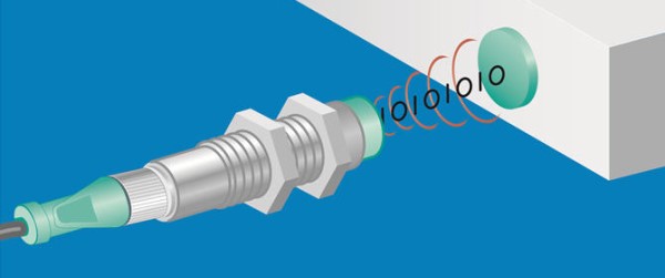
They send radio waves to the target, which responds by sending back a 32 or 64 bit binary code to the sensor; the sensor will activate its output only when it receives the same code with which it was programmed by the manufacturer. There are RFID sensors with two-channel output and self-diagnosis that can reach PL e or SIL 3 even with a single sensor.